

This past weekend I had the great pleasure of competing at NERC‘s Motorama Robot Conflict with my fighting robot Such and Such – built 100% at Hive76.
Though it might have looked a little boring, that was the most exciting match of the competition for me. After 2 years of on-and-off work, Such and Such, the most ambitious robot I’ll ever build, worked like a charm.
And still it only barely managed to eek out a win. To put it simply, Such and Such was not designed to beat other robots. At least, not on its own; it’s actually meant to fight alongside a partner hammer-bot, but weight limits prevented our tag team strategy. Rather, the point of Such and Such was to come up with the most overtly weird fighting robot possible, and then design it and build it.
The two main features of the robot that make it kind of unique are the walking and clamping mechanisms. A great deal of time was spent in the design phase figuring out how best, and in fact how easiest to implement these ideas.
Walking
There were a few reasons I chose to make Such and Such a walking robot. First, there aren’t enough walking robots and this was a way to make the whole thing wackier. Secondly, I wanted to increase the bot’s traction (I was previously using omniwheels to accommodate the sideways motion of the clamping action – unfortunately, omniwheels tend to have poor traction, so omni-legs seemed like an acceptably ridiculous alternative). Additionally, walking robots are allowed a 50% weight bonus, and I hoped to have a little left over to afford all this additional complicated mechanical nonsense.
The walking mechanism is basically a set of three crankshafts with a series of cam profiles that ride in slots on three legs. The legs have a phase difference of 120 degrees, so each rotation of the shaft provides about three “shuffles”.
Many walkers of this type rely on eccentric circles for cam profiles, resulting in sinusoidal x-and-y movement of the legs. That is to say, the up-and-down (y) and back-and-forth (x) position of the legs is never the same instant-to-instant. This means that the robot’s frame will constantly be oscillating up and down above the floor as it walks forward. Since both halves of Such and Such are so far apart, I thought this might result in some weird binding forces on the clamping mechanism.
I wondered if there was a way for the robot to stay at a constant height off the ground as it walked. It would require the y-motion of the legs to switch and hold between “up” and “down” positions. That would prevent any binding of the clamping mechanism, plus it sounded like a pretty cool challenge. Conversely, the sinusoidal motion from a regular eccentric circle would have a leg continuously in motion between “up” and “down”, instantly reversing its travel once it reached those extreme points. After a bit of research and some time sketching on graph paper, I arrived at the following cam profile.

As it rotates in the leg slot, it holds the leg in the “down” position (in contact with the ground) for 120 degrees, then transitions and pushes the leg up for 60 degrees in to the “up” position. It stays there for another 120 degrees. Then the next 60 degrees of the leg return it back to the “down” position. With a series of 3 legs and cams 120 degrees out of phase with eachother, there would always be a leg being held in the “down” position, and the chassis would – in theory – stay at a constant height above the floor.

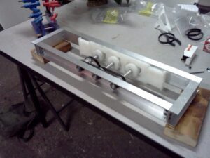
All of this up-and-down motion happens in conjunction with some back-and-forth motion to create a walking cam. Looking at the picture of the cams in the slots, it’s visible that the outer two cams are the binary y-motion (up and down) cams, while the center is an eccentric disk providing sinusoidal x-motion (back and forth). So as you can imagine, there’s quite a lot of sliding motion going on inside of these things.
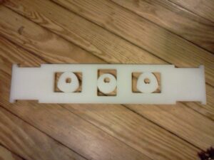
A big part of good design, or good anything, is to know your limits. Knowing that I could not make these cams and legs with the necessary precision, nor in the quantity required, I had the nice folks at Big Blue Saw low-taper waterjet them out of 1/2″ UHMW for me. Once they arrived I buffed all the sliding surfaces to get them to a smooth, low friction finish. After a quick test to verify the cam worked as expected, I ordered the rest of the batch.
Clamping
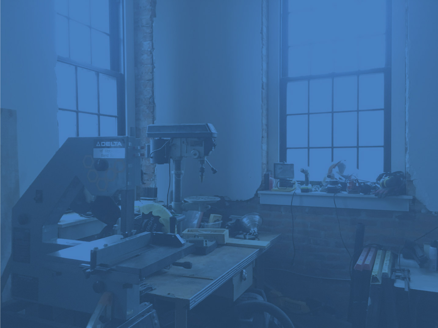
The last version of Such and Such had a really cool pantograph-type clamping mechanism much like a scissor lift on its side. It was fun, but a pain to deal with the linear motion at either end of the linkages. Sliding joints are a little harder to pull off than a bunch of pinned joints, so I thought I’d like to avoid it altogether. I also wanted this version to have fewer links for the same amount of horizontal travel as it’s a slightly more efficient use of weight. I settled on the following mechanism:

Looked pretty cool to me. Only 4 links and a great deal of horizontal travel. But little did I realize at the time that there was a fatal flaw in the design… but more on that later. I kept the the linear actuator external to the bot so that each half can be as small as possible, only about as wide as the walking bits. Conveniently, there was a nice little space for the actuator betwen the links in both open and closed positions. I did a little bit of math to find an optimal-ish offset angle (α) for the actuator to drive the rear link at so that the clamping force is mostly constant throughout the mechanism’s whole travel.


Construction
Construction commenced on December 1st 2012, just as I finished up my 8mm Projector Tremolo project. I made simple drawings of all the frame members and got to cutting all the lengths of 3/4″ angle and 2″x1″ U-channel that comprise the frame halves.

Next, all the frame members were drilled out to accomodate brackets and bearings.

After testing on a prototype leg and cam set, I ordered a full batch. One of the most time consuming parts of the project was cutting, drilling, and mounting the 48 little roller brackets onto the legs.

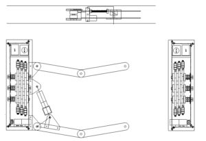
Next came the delicate task of stacking the three sets of UHMW cams, legs and spacers on three shafts, and then repeating the process for the other half of the bot. I decided not to lubricate the cams since most references indicated that polished UHMW is sufficiently self-lubricating, and grease may only trap dirt and debris. I drilled some well-oversized holes to allow some play in mounting the self-aligning bearings for the camshafts – since the phase of the cams was of utmost importance to the mechanism, I let the timing belts locate the bearings’ exact position.

After another order of waterjetted parts (this time aluminum), I assembled the linear actuator and attached linkage pivot points to the frames.

With the frame halves and walking mechanism mostly taken care of and smoothed out, I switched my focus to the clamping mechanism.

However, as soon as I laid out the links in front of me, I realized I’d made a grevious mistake. What I failed to realize in the design phase is that the linkage has way too many degrees of freedom. What that means is, I could move that one link back and forth all I want with the linear actuator, but the rest of the mechanism is gonna flop around however it likes and not clamp at all! As a mechanical engineer, this is quite the oversight and really really embarassing. In my mind, I just had assumed for so long that the two halves of the bot stayed parallel to eachother as the mechanism opened and closed. In reality, there was nothing constraining them to this kind of motion. 3 weeks out from the competition I had to come up with a quick fix in the form of some secondary links and a sliding pivot in the center of the whole thing. If these parts look like an afterthought, they were!

After such an embarassing mistake I found it helpful to walk away from the build for a little and let my mental faculties simmer down a bit. Thankfully all the major hurdles in the build had been crossed by this point and before I even realized it I was ready to install drive motors and wire it up.

 I even had time to add a neat hinged battery compartment to make charging way easier. Before I even got to the competition, I had considered the build a success: it walked and it clamped. I came up with just about the wackiest idea I could, I built it, and it worked. So now it’s back to cheap, simple robots. Maybe.
Here’s another video – this time with Charles Guan‘s incredible Uberclocker Advance, during which Such and Such spends alot of time off the ground.
(Check out Mike Jeffries’ YouTube channel for basically all the fights from the competition!)
Huge thanks to NERC for putting on great events, Alan Young for his generous help with blown up motors, Josh Frisch for being a patient teammate, my Dad, Michael Jeffries for the video, Hive76, and the entire robotics community for being such a righteous bunch of folks.
This is the longest post ever. I love it for sheer volume. Also robots. ROBOTS and GIFS